ÙˆَÙ…َا Ù‡َٰذِÙ‡ِ ٱلْØ­َÙŠَÙˆٰØ©ُ ٱلدُّÙ†ْÙŠَآ Ø¥ِÙ„َّا Ù„َÙ‡ْÙˆٌ ÙˆَÙ„َعِبٌ ۚ ÙˆَØ¥ِÙ†َّ ٱلدَّارَ ٱلْØ¡َاخِرَØ©َ Ù„َÙ‡ِÙ‰َ ٱلْØ­َÙŠَÙˆَانُ ۚ Ù„َÙˆْ Ùƒَانُوا۟ ÙŠَعْÙ„َÙ…ُونَ

“Dan tiadalah kehidupan dunia ini melainkan senda gurau dan main-main. Dan sesungguhnya akhirat itulah yang sebenarnya kehidupan, kalau mereka mengetahui.” (QS. Al-Ankabut:64)

Selasa, 16 Juni 2020

Arsitektur Komputer:Pertemuan 12-Reduced Insruction Set Computer

Reduced Instruction Set Computer (RISC)
  • Arsitektur RISC merupakan kemajuan yang sangat dramatis dalam frase sejarah arsitektur CPU. Dan  merupakan tantangan yang sangat dramatis dalam frase sejarah arsitektur CPU. Dan merupakan tantangan
  • bagi arsitektur konvensional.Walaupun sistem RISC telah ditentukan dan dirancang dalam berbagai cara berdasarkan kelompok-kelompoknya, elemen penting  yang di gunakan oleh sebagian rancangan adalah kelompok-kelompoknya, elemen penting  yang di gunakan oleh sebagian rancangan adalah sebagai berikut :
  • Set instruksi yang terbatas dan sederhana
  • Register general purpose yang berjumlah banyak, atau penggunaan teknologi kompiler untuk  penggunaan teknologi kompiler untuk mengoptimalkan pemakaian registernya
  • Penekanan pada pengoptimalan pipeline instruksi
1. Karakteristik karakteristik Eksekusi Instruksi
  • Salah satu bentuk evolusi komputer yang paling di rasakan adalah adalah evolusi bahasa pemrograman
Karakteristik dari beberapa prosesor CISC, RISC dan Superskalar


Karakteristik RISC

Karakteristik Super Skalar

Aspek-aspek Komputasi
Untuk memahami RISC harus diawali dengan tinjauan singkat tentang
  • Untuk memahami RISC harus diawali dengan tinjauan singkat tentang  karakteristik eksekusi instruksi.
  • Aspek-aspek komputasi yang dimaksud  adalah sebagai berikut :
A. Operasi-operasi yang di lakukan
B. Operand-operand yang di gunakan
C. Pengurutan eksekusi
B. Operand-operand yang

A.Operasi
B.Operand

2. Penggunaan File Register Besar
  • Alasan diperlukannya penyimpanan register adalah dengan melihat kenyataan bahwa menyimpan  register merupakan perangkat penyimpan paling cepat, yang lebih cepat dibandingkan dengan  register merupakan perangkat penyimpan paling cepat, yang lebih cepat dibandingkan dengan  memori utama dan memori cache.
  • File register secara fisik berukuran kecil, dan  umumnya berada pada satu keping dengan ALU dan Control Unit dan hanya memakai alamat yang  umumnya berada pada satu keping dengan ALU dan Control Unit dan hanya memakai alamat yang  lebih pendek dibandingkan dengan alamat-alamat cache dan memori lebih pendek dibandingkan dengan alamat-alamat cache dan memori
  • Dengan demikian, di perlukan strategi yang dapat menjaga operand-operand yang dapat menjaga operand-operand yang paling sering di akses tetap di dalam  yang paling sering di akses tetap di dalam  register dan untuk meminimalkan operasioperasi register memori.
  • Dalam mamaksimalkan register dipakai 2 pendekatan
  1. Pendekatan perangkat lunak
  2. Pendekatan perangkat keras
3. Register Windows
  • Penggunaan register dalam jumlah yang besar akan mengurangi kebutuhan mengakses memori besar akan mengurangi kebutuhan mengakses memori
  • Dalam hal ini tugas perancang adalah mengatur register-register sedemikian rupa  sehingga tujuan dapat tercapai sehingga tujuan dapat tercapai.
4. File Register Berukuran Besar VS Cache
  • File register yang diorganisasikan menjadi dua jendela, berfungsi sebagai buffer kecil yang cepat  untuk menampung subset seluruh variabel yang memiliki kemungkinan besar akan banyak di pakai.
  • File register berfungsi lebih menyerupai cache memori
  • File register dapat tidak efesian dalam menggunakan ruang, karena tidak semua prosedur akan memerlukan ruang jendela sepenuhnya yang telah diberikan.
  • File register dapat tidak efesian dalam menggunakan ruang, karena tidak semua  menggunakan ruang, karena tidak semua prosedur akan memerlukan ruang jendela  prosedur akan memerlukan ruang jendela sepenuhnya yang telah diberikan   sepenuhnya yang telah diberikan  
  • Sebaliknya cache memiliki ketidak efisienan lainnya yaitu
    • Data akan di baca kedalam cache  dalam bentuk blok-blok.
    • Sedang file register hanya berisi variabel-variabel yang sedang di gunakan.
    • Cache membaca suatu blok data, yang mungkin sebagian darinya tidak akan di gunakan Cache memiliki kemampuan untuk menangani variabel global dan juga variabel lokal
File Register Besar Vs Cache

5. Otimasi Register Berbasis Kompiler
  • Pada mesin RISC hanya tersedia register dalam jumlah yang sedikit (16-32 buah)
  • Disini penggunaan register yang telah di optimalkan tersebut merupakan tenggung jawab kompiler
  • Fungsi kompiler adalah untuk menjaga operand  bagi komputasi sebanyak mungkin di dalam register  dan bukannya di dalam memori utama. 
  • Hal itu ditujukan untuk meminimalkan operasi load dan store
6. Karakteristik CISC Vs RISC
  • Rancangan RISC dapat memperoleh keuntungan dengan mengambil sejumlahfeature CISC
  • Rancangan CISC dapat memperoleh  keuntungan dengan mengambil sejumlah feature RISC
Ciri-ciri RISC :
  1. Instruksi berukuran tunggal
  2. Ukuran yang umum adalah 4 Byte
  3. Jumlah mode pengalamatan data yang sedikit ( < 5 buah)
  4. Tidak terdapat pengalamatan tak langsung
  5. Tidak terdapat operasi yang menggabungkan operasi  load / store dengan operasi aritmetika
  6. Tidak terdapat lebih dari satu operand beralamat memori per instruksi
  7. Tidak mendukung perataan sembarang, bagi data untuk operasi load/store
  8. Jumlah maksimum pemakaian memori management Unit (MMU) bagi suatu alamat data adalah sebuah instruksi management Unit (MMU) bagi suatu alamat data adalah sebuah instruksi
  9. Jumlah bit bagi register specifier sama dengan lima atau lebih
  10. Jumlah bit floating point register specifier empat atau lebih
7. Kontroversi RISC dan CISC
  • Tidak terdapat mesin-mesin RISC dan CISC yang sebanding dalam hal harga, tingkat teknologi,kompleksitas gate, kecanggihan kompiler dsb
  • Tidak terdapat pengujian program yang pasti. Kinerja bervariasi sesuai dengan programnya
  • Kesulitan dalam mengumpulkan akibat-akibat yang  di sebabkan perangkat keras yang berkaitan dengan keterampilan dalam membuat kompiler
  • Kesulitan dalam mengumpulkan akibat-akibat yang di sebabkan perangkat keras yang berkaitan dengan keterampilan dalam membuat kompiler berkaitan dengan keterampilan dalam membuat kompiler
  • Sebagian besar analisi komperatif tentang RISC  dilakukan pada mesin-mesin “mainan” bukannya pada mesin-mesin komersial. Selain itu,   bukannya pada mesin-mesin komersial. Selain itu, memiliki  sebagian besar mesin yang tersedia secara komersial dan di iklankan sebagai RISC memilik  karakteristik campuran antara RISC dan CISC. Dengan demikian, perbandingan yang adil  dengan mesin CISC komersial dan murni sangatlah sulit di laksanakan.
  • Dalam beberapa tahun terakhir,  kontroversi RISC dangan CISC semakin berkembang.
  • Hal ini disebabkan karena terjadinya semakin konvergensinya teknologi.
  • Dengan semakin bertambahnya kerapatan keping dan semakin cepatnya perangkat keras,  maka sistem RISC menjadi semakin komplek.
  • Bersamaan dengan hal itu, untuk mencapai kinerja yang maksimum, Rancangan CISC telah di fokuskan terhadap masalah-masalah  kinerja yang maksimum, Rancangan CISC tradisional yang berkaitan dengan RISC, seperti misalnya pertambahan jumlah register general  purpose dan penekanan pada rancangan pipeline instruksi


    Latihan Pertemuan 12


Kamis, 11 Juni 2020

Jaringan Komputer:Pertemuan 11- Seven Layer OSI


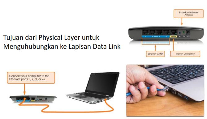
Physical Layer
Data Link Sublayer
  • LLC berkomunikasi dengan lapisan jaringan
  • MAC mendefinisikn media akses proses
Standar Data Link Layer
  • IEEE
  • ITU
  • ISO
  • ANSI
Network Layer
Protokol Network Layer
  • IPv4
  • IPv6

Transport Layer
  • Peran Transport Layer
➢Membangun komunikasi antara dua aplikasi dan memberikan data di antara mereka.
➢Memberikan dukungan aliran data, kontrol Flow, Multiplexing
  • Keandalan Transport Layer
➢Dua protokol yang tersedia: TCP dan UDP.
➢TCP mendukung kehandalan sementara UDP tidak.

Transportasi Data
  • TCP biasanya digunakan untuk,
➢ Database
➢ Web Browser
➢ Mail, dll
  • UDP
➢ Live Audio
➢Video Streaming
➢Voip, dll

Application, Presentation, Session
  • Application Layer
➢Lapisan yang paling dekat kepada pengguna.
➢Yang termasuk Protokol Application Layer adalah: HTTP, FTP, TFTP, DNS.
  • Presentation dan Session Layer
➢Format data, kompres dan mengenkripsi data
➢Umumnya digunakan untuk video termasuk QuickTimedan Motion Picture Experts Group  (MPEG).
➢Format gambar grafis umum adalah: GIF, JPEG dan PNG
➢Session Layer menciptakan dan mempertahankan dialog  antara sumber dan tujuan aplikasi.

Application Layer Protocol
IP Address
  • Domain Name Service
➢Dengan menggunakan DNS Server membuat alamat IP lebih  mudah di hapal.
➢Komputer masih memerlukan alamat numerik yang sebenarnya sebelum mereka dapat  berkomunikasi.
➢Protokol DNS memungkinkan untuk menerjemahkan alamat IP menjadi sebuah domain.

  • Dynamic Host Configuration Protocol
➢Jaringan komputer memerlukan informasi IP address untuk berkomunikasi melalui jaringan.
➢DHCP memungkinkan untuk memberikan IP address  secara otomatis.
➢DHCP mendukung IPv4 dan mendukung DHCPv6  IPv6.

DHCP Server
DHCP Client
Untuk mendapatkan service  DHCP server. Pastikan Client memilih IP Configuration DHCP
===============================================
Tugas Mandiri
  1. Jelaskan Fungsi-Fungsi dari Protokol di bawah ini:
    a) ICMP
    b) POP3
    c) SMTP
    d) FTP
    e) ARP
  2. Berikan Penjelasan Mengenai kelebihan dan Kekurangan Ipv4 dan Ipv6?
  3. Tugas di upload via blog masing-masing mahasiswa dan alamat blog tampilkan di post comment

Arsitektur Enterprise:Pertemuan 11-Metode ADM,Fase Pada TOGAF ADM

Metode ADM
Metode pada ADM dibagi menjadi delapan sequential phases (A to H) dan dua phase khusus lainnya: preliminary phase dan requirements management phase. Gambar 1 menampilkan diagram TOGAF yang paling sering dirujuk, yang merangkum pendekatan ini melalui pemecahan empat bagian tingkat tinggi: bisnis, teknologi informasi (TI), perencanaan, dan perubahan. Urutan fase A ke H dipecah sebagai berikut:
Semua phases dideskripsikan seperti ini:

Meskipun perkembangan fase dijelaskan secara berurutan (dari A ke H), urutan ini dapat ditinjau dan disesuaikan sesuai dengan konteksnya, terutama dalam bentuk iterasi dalam siklus ADM.
Gambar 1. Architecture development method (ADM)—TOGAF

  • Meskipun perkembangan fase dijelaskan secara berurutan (dari A ke H), urutan ini dapat ditinjau dan disesuaikan sesuai dengan konteksnya, terutama dalam bentuk iterasi dalam siklus ADM. Secara lebih umum, diagram “crop cycle" harus dianggap sebagai struktur referensi alih-alih suatu perkembangan yang tidak berubah, terutama karena tetap mungkin, dan bahkan lebih disukai, untuk mempertanyakan atau menyesuaikan kapan saja bagian dari hasil yang diperoleh sebelumnya.
  • Identifikasi dari kendala baru atau formulasi ulang atau penambahan rincian persyaratan dapat menyebabkan aspek baru tertentu muncul, aspek yang tidak cukup dieksploitasi selama fase  sebelumnya. Sebagai contoh, dokumen keluaran utama fase A, “architecture vision,” hanya divalidasi secara definitif selama fase F. Namun, high-quality elaboration menyiratkan perkembangan konvergen, yang tidak mempersoalkan prinsip-prinsip dan foundations yang didefinisikan pada permulaan.
Gambar 2. Typical path of an ADM cycle.
  • Figure presents an overview of the progression of an ADM cycle, from the preliminary phase right through to phase H. This typical path is guided by one major goal: the need to obtain the expected result by mastering each step of the process. This goal requires rigorous preparation, a description of the target with regard to what already exists for all facets (business, information system, and technology), precise evaluation of the gaps and risks determining the choice of trajectory, and finally evaluation of the results and careful management of any adjustments made.
  • TOGAF describes each step of each phase in detail. This does not mean that the realization of each of these steps is systematic. Some results are already available, either because they are produced by other entities or because they are linked to more general activities. For example, if architecture principles are recorded as results from phase A, they can simply be checked where they already exist. The main thing here is that the presence and conformity of each result must be checked, just like a checklist associated with each phase.
Fase-Fase Pada TOGAF ADM
1. The preliminary phase
Tujuan pada phase ini adalah untuk mempersiapkan enterprise untuk merealisasikan pekerjaan architecture :
  • The organization and governance of the architecture
  • General principles
  • Methods
  • Tools
  • The architecture repository
  • The start of the ADM cycle
Dengan cara ini, preliminary phase bukan bagian dari siklus ADM tetapi dapat dipertimbangkan kapan saja selama siklus ADM sebagai bagian dari evolusi praktik EA, terutama dalam konteks menggunakan maturity model sebagai cara mengidentifikasi peluang untuk inisiatif transisi. Kegiatan pada preliminary phase pada dasarnya cross-organizational, terkait dengan tata kelola umum arsitektur perusahaan, dan tujuannya adalah untuk memungkinkan perusahaan menguasai manajemen dan transformasi arsitekturnya. Namun, selama fase pendahuluan itulah dimulainya siklus ADM tertentu dan disiapkan. Ini dirinci dalam dokumen "Request for Architecture Work", yang berisi semua elemen yang membentuk dasar dari proyek perubahan arsitektur perusahaan (sponsor, tujuan strategis, kendala, kerangka anggaran, dan rencana strategis). Dokumen ini merupakan panduan referensi kontrak untuk kemajuan seluruh siklus TOGAF itu sendiri, dari fase A dan seterusnya.

2. Phase A (vision)
Phase A is the first phase of the ADM cycle, triggered by the validation of the “Request for Architecture Work” document. Phase A has two main goals:
  • First, phase A further develops and enriches elements resulting from the preliminary phase, such as architecture principles, key indicators, and the organization or planning of elaboration work.
  • Second, phase A prepares subsequent phases by providing a general representation of the baseline andtarget architectures. At this stage, these remain high-level representations, whose goal is to highlight structuring points and typical solutions.
Communication plays a key role during this phase. All stakeholders must have the same understanding, in order to obtain consensus on orientations and expected results. Other points are also dealt with, such as the identification of fundamental requirements, their links to strategic goals, or risk management. The “Architecture vision” document constitutes the main output of this phase. To sum up, at the end of phase A we have a common vision of:
  • Organization: the stakeholders, their roles, their respective involvement
  • Orientation: a consensus on the principles, goals, major requirements, and constraints
  • The scope covered, the most impacted parts
  • The roadmap: the ADM cycle development plan, the resources, and the budget allocated
  • A macroscopic vision of baseline architecture and target architecture
  • Major risks and associated risk reduction actions
In other words, we know where we’re going, how we’re getting there, and with whom. Note that at this stage the perspective is horizontal, and covers all architecture domains (business, information system, and technology), unlike the following three phases, which operate vertically, focusing on one particular domain.

3. Phases B, C, and D (Elaboration of Business, Information System, and Technology Architectures)
  • Most of the content of the following three phases—B (Business), C (Information System), and D (Technology)—consists in detailing the target and baseline architecture, measuring the gap between the two, and evaluating the impact of change on all facets of the enterprise. The combination of these elements is used to draft the roadmap for transition. This first draft of the roadmap is elaborated progressively throughout phases B, C, and D, and serves as the foundation for phases E and F, which are in charge of defining the transformation plan (Figure 3).
  • Each phase begins with the definition of the views that will be used to materialize the baseline and target architectures. Remember that the goal of these views is to adapt the representations of the architecture to each stakeholder’s viewpoint.
  • Architecture descriptions are consigned to the architecture definition document (central document). This document is enriched during each phase, before being finalized and validated prior to the start of migration work. Concretely, each phase will complete the chapter(s) that concerns it, so that the document spans all architecture domains.
  • Of course, as well as depending on each situation, the choice of target architecture also integrates recurrent questions. Consequently, TOGAF recommends that the repository be reviewed before each decision in order to reuse the experience accumulated during earlier work wherever possible. This repository review is noted as a “checklist” action at the start of each phase, so as to conform to the norms in place within the enterprise and to promote general harmonization.
Gambar 3. Main activities common to phases B, C, and D.

Impact assessment should be considered in a cross-organizational way, for two reasons. First, because each phase evaluates its impact beyond its own scope. During phase B, for example, the impact of evolutions on technical elements is also assessed. If, for example, the executive management team decides to remove a product range, it is easy to work out the consequences of this decision on the corresponding database. Second, because the sheer number of relationships within an enterprise can lead to all sorts of unexpected side effects on entities outside the initial scope.

Phase B (business architecture)
The structural similarity of phases B, C, and D should not detract from the determining role of phase B, since it is the business that drives the architecture in all its forms. The formalization of business elements (requirements, processes, entities) is the prelude to all valid logical or technical constructions. This is all the more true when we consider that the goal of phase B is also to demonstrate the pertinence of the work being carried out. Goals are established during the earlier phases, but it is only when business architecture elements are precisely developed that the target solution can be installed and its consequences observed. For example, the description of modifications carried out on a business process shows the real-life result of these modifications on tasks run by operators, new services to provide, or modifications applied to exchanged information.

In terms of architecture descriptions, phase B mainly concentrates on the following elements:
  • Business motivation elements (drivers, goals, objectives)
  • Organizational units
  • Business functions and services
  • Business processes
  • Business roles and actors
  • Business entities
Business entities describe key business concepts and provide the essential entry point to phase C (in the Data Architecture subphase). Business processes are often the key to understanding an enterprise’s real activity, and by extension its architecture.

Phase C (information systems architecture)
Information system architecture is a kind of bridge between the business view and its physical translation. It defines software components (applications and data) that support the automation or realization of business capabilities and functions, without integrating technological realities (this point is dis-cussed in the Phase D part).

Remember that phase C (information system architecture) is itself composed of two subphases: data architecture and application architecture.

These two facets (data and application) are reunited in a single phase because of their proximity in the construction of information system architecture. One of the  expected results consists in allocating each data group to one application  component, which will handle its management, becoming, as it were, the owner  of the data group in question.

Phase D (technology architecture)
  • Unsurprisingly, the role of phase D is to establish the technological and physical correspondence of the elements developed during the previous phases. In particular, technology architecture defines the platforms and execution environments on which the applications run and the data sources are hosted for use.
  • So what are the links between application architecture and technology architecture? A first approach consists in considering them as two separate elements, so as to avoid any technical “intrusion” into the work of the application architect. The opposite approach would lead us to consider application architecture as a simple reformulation of the technical reality.
  • A position that is too dogmatic will lead to a dead end: What is the point of developing a “virtual” application architecture with no link to the reality of the deployed applications? Common sense (and purse strings) calls for more realism. Even though it must remain logical, application architecture (including its service-oriented architecture (SOA) formulation) is not completely separate from its physical translation. The most important thing here is the identification of the role of each application or component, independent of its technical implementation: the fundamental structure is similar and the viewpoint is different, just like a logical service interface, which is not fundamentally modified by its implementation in Java or via a web service.
  • Bearing in mind these two perspectives, a question comes to mind: Should we start by describing the technical architecture or the application architecture? This point is linked to the iterations of the ADM cycle, which will be more generally dealt with in Section 2.3. Remember that the ADM
    cycle is a generic framework, which does not forbid intrusions into earlier or later phases (the TOGAF document is strewn with suggestions of this type). In practice, no preestablished choices exist: this is the famous choice between “top down” and “bottom up,” which always finishes with a compromise. The deployment of external tools imposes a type of architecture that can sometimes have a significant impact on application architecture solutions. In other contexts, architecture will be more oriented by architectural principles, for example to obtain a more progressive structure.
  • However, let’s get back to the result of phase D: the technological architecture, in other words, a coherent set of software components, infrastructures, and technical platforms. These elements can come from external providers or be produced directly by teams within the enterprise. Moreover, the choice between deploying tools that are available in the marketplace or tools resulting from specific developments is a recurrent theme for an enterprise architect. Here too, the repository will assist in this type of choice by making available a set of common norms, patterns, tools, and practices, which will help harmonize solutions within the enterprise.
4. Phases E and F (opportunities and solutions, migration planning)
  • At this point of the ADM cycle, the operational realization of architecture transformation truly begins: projects are set up, schedules defined, resources identified, and operational monitoring put in place. The previous phases have provided the target, an overall roadmap, and now their concrete implementation has to be defined.
  • Phases E and F look at the scheduling and organization of the implementation of new architecture.  mphasis is placed on building the migration path, which must bring true business benefit to each step.
  • During phase E, the results of the elaboration phases (B, C, and D) are consolidated: architectures, requirements, and gaps. This consolidation constitutes the raw material used to define transition architectures, while bearing in mind the enterprise’s capability for change (for example, new applications to develop and evolutions of existing applications, according to the coverage of the business functions). Technical and organization feasibility, compromises between requirements and costs, and integration constraints are also studied.
  • Phase F precisely establishes migration scheduling, as well as the constitution of implementationprojects and their organization, goals, and costs.
  • Phase F precisely establishes migration scheduling, as well as the constitution of implementation projects and their organization, goals, and costs.
5. Phases G and H (implementation governance, architecture change management)
  • Phase G establishes the definitive version of architecture contracts with implementation projects, including recommendations from the architecture board. These signed contracts constitute the basis for conformity reviews of implementation projects.
  • Phase H handles the management of the deployed architecture: change management, including the evaluation of change requests that impact the architecture. It should be noted that certain evolution requests can lead to new ADM cycles.

Selasa, 09 Juni 2020

Routing & Switching Essentials: Pertemuan 11-DHCP


Packet Tracer - Configuring DHCP Using Cisco IOS

Addressing Table

Device

Interface

IPv4 Address

Subnet Mask

Default Gateway

R1

G0/0

192.168.10.1

255.255.255.0

N/A

S0/0/0

10.1.1.1

255.255.255.252

N/A

R2

G0/0

192.168.20.1

255.255.255.0

N/A

G0/1

DHCP Assigned

DHCP Assigned

N/A

S0/0/0

10.1.1.2

255.255.255.252

N/A

S0/0/1

10.2.2.2

255.255.255.252

N/A

R3

G0/0

192.168.30.1

255.255.255.0

N/A

S0/0/1

10.2.2.1

255.255.255.0

N/A

PC1

NIC

DHCP Assigned

DHCP Assigned

DHCP Assigned

PC2

NIC

DHCP Assigned

DHCP Assigned

DHCP Assigned

DNS Server

NIC

192.168.20.254

255.255.255.0

192.168.20.1

Objectives

Part 1: Configure a Router as a DHCP Server

Part 2: Configure DHCP Relay

Part 3: Configure a Router as a DHCP Client

Part 4: Verify DHCP and Connectivity

Scenario

A dedicated DHCP server is scalable and relatively easy to manage, but can be costly to have one at every  location in a network. However, a Cisco router can be configured to provide DHCP services without the need for a dedicated server. Cisco routers use the Cisco IOS feature set, Easy IP, as an optional, full-featured DHCP server. Easy IP leases configurations for 24 hours by default. As the network technician for your company, you are tasked with configuring a Cisco router as a DHCP server to provide dynamic allocation of addresses to clients on the network. You are also required to configure the edge router as a DHCP client so that it receives an IP address from the ISP network.

Part 1:     Configure a Router as a DHCP Server

Step 1:     Configure the excluded IPv4 addresses.

Configure R2 to exclude the first 10 addresses from the R1 and R3 LANs. All other addresses should be available in the DHCP address pool.

Step 2:     Create a DHCP pool on R2 for the R1 LAN.

a.     Create a DHCP pool named R1-LAN (case-sensitive).

b.    Configure the DHCP pool to include the network address, the default gateway, and the IP address of the DNS server.

Step 3:     Create a DHCP pool on R2 for the R3 LAN.

a.      Create a DHCP pool named R3-LAN (case-sensitive).

b.    Configure the DHCP pool to include the network address, the default gateway, and the IP address of the DNS server.

Part 2:     Configure DHCP Relay

Step 1:     Configure R1 and R3 as a DHCP relay agent.

Step 2:     Set PC1 and PC2 to receive IP addressing information from DHCP.

Part 3:     Configure R2 as a DHCP Client

a.     Configure the Gigabit Ethernet 0/1 interface on R2 to receive IP addressing from DHCP and activate the interface.

Note: Use Packet Tracer’s Fast Forward Time feature to speed up the process or wait until R2 forms an EIGRP adjacency with the ISP router.

b.    Use the show ip interface brief command to verify that R2 received an IP address from DHCP.

Part 4:     Verify DHCP and Connectivity

Step 1:     Verify DHCP bindings.

R2# show ip dhcp binding

IP address       Client-ID/              Lease expiration        Type

                 Hardware address

192.168.10.11    0002.4AA5.1470           --                     Automatic

192.168.30.11    0004.9A97.2535           --                     Automatic

Step 2:     Verify configurations.

Verify that PC1 and PC2 can now ping each other and all other devices.


Penyelesaian:

Part 1: Configure a Router as a DHCP Server

Step 1: Configure the excluded IPv4 addresses.

Configure R2 to exclude the first 10 addresses from the R1 and R3 LANs. All other addresses should be available in the DHCP address pool.

R2(config)# ip dhcp excluded-address 192.168.10.1 192.168.10.10

R2(config)# ip dhcp excluded-address 192.168.30.1 192.168.30.10

Step 2: Create a DHCP pool on R2 for the R1 LAN.

  1. Create a DHCP pool named R1-LAN (case-sensitive).
    • R2(config)# ip dhcp pool R1-LAN
  2. Configure the DHCP pool to include the network address, the default gateway, and the IP address of the DNS server.
    • R2(dhcp-config)# network 192.168.10.0 255.255.255.0
    • R2(dhcp-config)# default-router 192.168.10.1
    • R2(dhcp-config)# dns-server 192.168.20.254

Step 3: Create a DHCP pool on R2 for the R3 LAN.

  1. Create a DHCP pool named R3-LAN (case-sensitive).
    • R2(config)# ip dh pool R3-LAN
  2. Configure the DHCP pool to include the network address, the default gateway, and the IP address of the DNS server.
    • R2(dhcp-config)# network 192.168.30.0 255.255.255.0
    • R2(dhcp-config)# default-router 192.168.30.1
    • R2(dhcp-config)# dns-server 192.168.20.254

Part 2: Configure DHCP Relay

Step 1: Configure R1 and R3 as a DHCP relay agent.

!R1
R1(config)# interface g0/0
R1(config-if)# ip helper-address 10.1.1.2
!R3
R3(config)# interface g0/0
R3(config-if)# ip helper-address 10.2.2.2

Step 2: Set PC1 and PC2 to receive IP addressing information from DHCP.

Part 3: Configure R2 as a DHCP Client

  1. Step 1: Configure the Gigabit Ethernet 0/1 interface on R2 to receive IP addressing from DHCP and activate the interface.
    • R2(config)# interface g0/1
    • R2(config-if)# ip address dhcp
    • R2(config-if)# no shutdown
    • Note: Use Packet Tracer’s Fast Forward Time feature to speed up the process or wait until R2 forms an EIGRP adjacency with the ISP router.
  2. Use the show ip interface brief command to verify that R2 received an IP address from DHCP.

Part 4: Verify DHCP and Connectivity

Step 1: Verify DHCP bindings.

R2# show ip dhcp binding

IP address            Client-ID/                   Lease expiration                     Type                                                       Hardware address

192.168.10.11        0002.4AA5.1470               —                                 Automatic

192.168.30.11        0004.9A97.2535                —                                Automatic

Step 2: Verify configurations.

Verify that PC1 and PC2 can now ping each other and all other devices.

Download Packet Tracert Pertemuan 11-DHCP

Arsitektur Komputer: Pertemuan 11-Struktur dan Fungsi CPU

1. Organisasi Processor
Hal-hal yang perlu dilakukan CPU adalah :
  1. Fetch Instruction = mengambil instruksi
  2. Interpret Instruction = Menterjemahkan instruksi
  3. Fetch Data = mengambil data instruksi
  4. Process Data = mengolah data
  5. Write data = menulis data

Agar dapat melakukan hal-hal diatas maka CPU perlu menyimpan data untuk sementara waktu
  • Agar dapat melakukan hal-hal diatas maka CPU perlu menyimpan data untuk sementara waktu
  • CPU harus dapat mengingat lokasi instruksi terakhir sehingga CPU akan dapat mengambil instruksi berikutnya.
  • CPU perlu menyimpan instruksi dan data untuk sementara waktu pada saat instruksi sedang di eksekusi. sementara waktu pada saat instruksi sedang di eksekusi.
  • Dengan kata lain CPU memerlukan memori internal berukuran kecil.
2. Organisasi Register
Register dalam CPU memiliki dua fungsi :
  1. User-visible Register
  2. Control dan Status Register
A. User-Visible Register
Adalah register yang dapat direferensikan dengan menggunakan bahasa mesin yang  dengan menggunakan bahasa mesin yang dieksekusi CPU

Terdiri dari :
  • General Purpose =dapat berisi operand  sembarang op-code
  • Data = hanya dapat dipakai untuk  menampung data
  • Alamat = dapat di gunakan untuk mode  pengalamatan tertentu
  • Kode-kode kondisi (flag) = bit-bit yang di setel perangkat keras CPU sebagai hasil operasi
B. Control dan Status Register
Adalah register-register yang digunakan oleh unit kontrol untuk mengontrol operasi  CPU dan oleh program sistem operasi untuk mengontrol eksekusi program CPU dan oleh program sistem operasi
untuk mengontrol eksekusi program

Terdapat empat buah register yang penting
  1. Program Counter (PC) berisi alamat instruksi yang akan berisi alamat instruksi yang akan  di ambil.
  2. Instructions Register (IR) berisi instruksi yang  berisi instruksi yang  terakhir diambil
  3. Memory Address Register (MAR) Berisi alamat sebuah lokasi di dalam memori
  4. Memory Buffer Register (MBR) Berisi sebuah word data yang akan dituliskan kedalam  memori atau word yang terakhir di baca
Program Status Word (PSW)
  • Semua rancangan CPU mencakup sebuah register atau sekumpulan register  sering kali disebut Program Status Word (PSW) yang berisi informasi status.
  • Biasanya PSW berisi kode kondisi dan informasi status lainnya
Common field atau flag meliputi hal-hal berikut ini:
  • Sign = berisi bit tanda hasil operasi aritmetika terakhir
  • Zero = disetel bila hasil sama dengan nol terakhir
  • Carry = disetel apabila operasi yang dihasilkan didalam carry (penambahan) kedalam bit yang lebih tinggi atau borrow (pengurangan) dari bit yang lebih tinggi
  • Equal = disetel apabila hasil pembandingan logikanya sama
  • Overflow = digunakan untuk mengindikasikan overflow aritmetika
  • Interrupt enable / disable = di gunakan untuk mengizinkan atau mencegah interrupt
  • Supervisor = mengindikasikan apakah CPU sedang mengeksekusi dalam mode supervisor atau dalam mode user.
3. Siklus Instruksi
A. Proses Tak Langsung
  • Eksekusi sebuah instruksi melibatkan sebuah operand atau lebih di dalam memori, yang masing-masing operand memerlukan akses memori
  • Apabila digunakan pengalamatan tak langsung, maka diperlukan akses memori tambahan
  • Kita dapat menganggap pengambilan alamat-alamat tak langsung sebagai   sebuah sub instruksi atau lebih.
  • Kegiatan utamanya terdiri dari aktifitasaktifitas pengambilan instruksi dan pengeksekusian instruksi.
  • Operand yang dibutuhkan diambil dengan menggunakan pengalamatan tak langsung
  • Setelah eksekusi dilakukan, interrupt dapat diproses sebelum mengambil instruksi berikutnya
Aliran data :
  • Pada saat pengambilan instruksi di baca dari memori
  • Dalam CPU, PC berisi alamat berikutnya yang akan diambil
  • Alamat ini di pindahkan ke MAR dan ditaruh di bus alamat
  • Unit control meminta pembacaan memori dan hasilnya disimpan di bus data dan disalin ke MBR dan kemudian di pindahkan ke IR
  • Sementara itu PC naik nilainya 1, sebagai persiapan untuk pengambilan selanjutnya.
  • Bila siklus pengambilan telah selesai, Unit kontrol memeriksa isi IR untuk menentukan apakah IR berisi operand specifier yang menggunakan
  • pengalamatan tak langsung
  • Apabila berisi operand maka dilakukan siklus tak langsung
4. Pipelining Instruksi
  • Efesiensi sebuah sistem komputer dinilai berdasarkan kecepatan perangkat keras dan fasilitas-fasilitas perangkat lunak.
  • Penilaian ini disebut dengan troughput =jumlah pemrosesan yang dapat dikerjakan dalam suatu interval waktu tertentu.
  • Salah satu teknik yang mendorong  peningkatan suatu sistem troughput yang cukup hebat disebut sebagai pemrosesan PIPELINE
  • Pemrosesan Pipeline dalam suatu komputer diperoleh dengan membagi suatu fungsi yang akan dijalankan menjadi beberapa sub fungsi
  • yang lebih kecil dan merancang perangkat keras yang terpisah (STAGE), untuk setiap sub fungsi.
  • Stage-stage itu kemudian bersama-sama membentuk pipeline tunggal untuk menjalankan fungsi asli
Sinkronisasi Pipeline
  • Pada semua baris perakitan industri, efesiensi suatu pipeline dapat berkurang jauh akibat suatu bottleneck.
  • Bottleneck terjadi sewaktu pemrosesan pada suatu stage, menghabiskan waktu lebih lama dari stage yang lain
  • Karena itu idealnya kita menginginkan pada semua stage menghabiskan waktu yang sama.
  • Untuk menyamakan waktu yang diperlukan pada setiap stage maka stage- stage tersebut harus di sinkronisasi.
  • Dapat dilakukan dengan menyisipkan kunci-kunci sederhana antara stage-stage tersebut.
Efisiensi Pipeline
  • Suatu fungsi pipeline hampir selalu lebih baik dari pada fungsi non-pipeline
  • Namun pada kenyataannya, harga pipeline tersebut sangat mempengaruhi kapan dan apakah fungsi-fungsi yang di pipeline-kan lebih baik atau tidak.
Beberapa penyebab harga pipeline :
  1. Tambahan kunci (latch) perangat keras yang dibutuhkan.
  2. Kendali yang diperlukan untuk penjadwalan input tersebut.
  3. Waktu yang dihabiskan oleh data dalam latch untuk menyesuaikan diri dengan suatu penangguhan clock yang seragam
  4. Jumlah rata-rata input yang tersedia
Klasifikasi Pipeline:
A. Klasifikasi berdasarkan Fungsi
  • Pipelining Aritmatika = Proses segmentasi fungsi dari ALU dari sistem yang muncul dalam kategori ini.
Pipelining Instruksi
  • Proses fetch pada instruksi tidak akan dimulai sampai eksekusi tidak akan dimulai sampai eksekusi instruksi sebelumnya selesai.
  • Untuk mem-pipelinekan fungsi ini, instruksiinstruksi yang berdampingan di fetch dari memori ketika instruksi yang sebelumnya di decode dan di jalankan.
  • Proses pipelining instruksi disebut instructions
Pipelining Prosessor
  • Sewaktu stage dari suatu stage merupakan merupakan prosessor aktual  dan latch-latch saling berbagi memori antara prosessor-prossor tersebut maka pipeline itu disebut sebagai pipeline prossor.
5. Register-register Processor Pentium
Gambar Unit Integer